


I've been working on a game side-project for the past year as a fun way to really deep dive into Rust, Amethyst, and different game dev topics such as AI, pathfinding, shaders, etc. The game utilizes an isometric 2.5D view much like SimCity 3000 or Civilization, all from pre-rendered sprites.
As I was working on the map generation and rendering, I found a couple tutorials that went through a basic isometric projection with tiles, but nothing that did it in a way that was generalizable to different view points. Due to the progress I've made thus far with my own game, I decided to do a little writeup (with examples!) to showcase how to go from a grid of points to an isometric projection with different orientations.
Below I have a full example that has been rebuilt in WebGL with different toggles to visualize each step of the transformation.
The code for the example is available here.
From grid to projection
Standard isometric projection has it where if we started with the front face of an object, it would be rotated 45 degrees around the vertical axis and then approximately 35 degrees around the horizontal axis. After these transformations, the objects should look roughly like the different shapes in the image below:
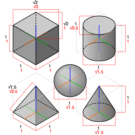 Example of different 3D shapes isometrically projected. Source: Wikipedia
Before we began, some assumptions:
- Tiles will be sprites that are already rendered with the isometric look (à la SimCity 3000).
- The tile grid is represented by a 2D array.
- The camera being used is an orthographic camera.
Assuming the grid to be in Euclidean space where (0,0) is
at the bottom left, the 2D array of tiles we'll be using in our example
will be represented roughly like the code snippet below:
1 enum Tiles = {
2 GRASS,
3 DIRT
4 };
5
6 let map = [
7 // row 0, col 0; row 0, col 1, etc.
8 [Tiles.GRASS, Tiles.GRASS, ...]
9 ...
10 ];
We can loop through each row and column and render each tile of the grid at
their respective (col, row) point to get something basic on screen.
1 let geometry = new THREE.PlaneGeometry( 32, 32 );
2
3 let even = new THREE.MeshBasicMaterial({ color: 0xff0000 });
4 let odd = new THREE.MeshBasicMaterial({ color: 0x00ff00 });
5
6 for (let y = 0; y < grid.length; y++) {
7 for (let x = 0; x < grid[y].length; x++) {
8 let tile = new THREE.Mesh(
9 geometry,
10 (x + y) % 2 ? even : odd
11 );
12
13 tile.position.x = x;
14 tile.position.y = y;
15
16 scene.add(tile);
17 }
18 }
When the above code is run (see the repo for the full code snippet), we'll get something that looks roughly like so:
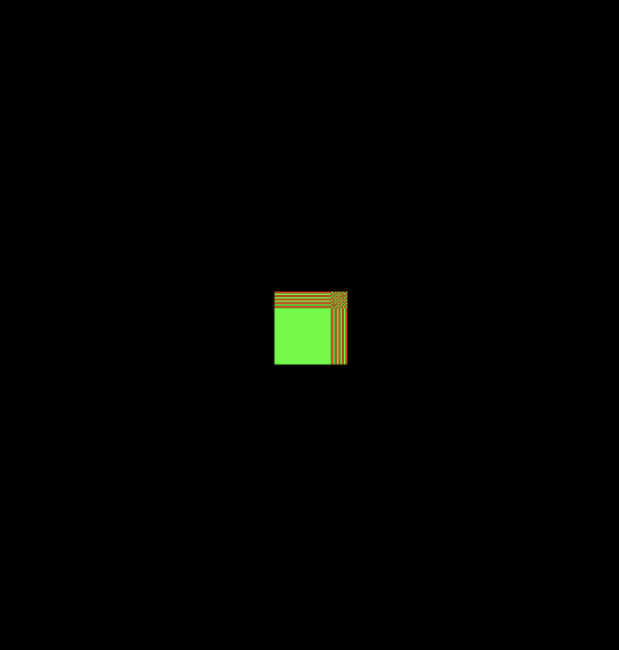 The example grid rendered with 32x32 width tiles at each respective
(col, row) point
As you can see, without any modification to how we place the tiles everything will overlap with each other. To go from this to the isometric projection we want, we're going to have to apply a series of transforms that will translate, scale, and rotate the tiles to their correct positions.
🤔 What are transforms?
In linear algebra, a transform or transformation matrix refers to a linear mapping between some set of points to another set of points. Typically, these linear transformations can be composed (i.e. applied one after another through multiplication) and inverted (e.g. to map a point back to some original grid).
In computer graphics, there are certain matrices that can be used to apply a rotation, scaling, or translation. It is with these matrices that we'll begin our journey towards the final isometric projection.
Applying the transforms
Since the sprites being used are already pre-rendered the isometric projection. We only need to apply the following transforms:
- Translating the grid such that the origin is in the center of the grid.
- Scaling the grid to match the sprite size.
- Rotating the grid around the vertical axis by 45 degrees.
Toggle between a combination of the 3 transformations in the full example at the beginning of the post to visualize how each transform affects the final tile placement.
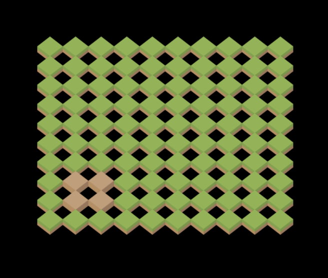
Above is an example of scaling the grid to the correct tile size, with the tiles attached
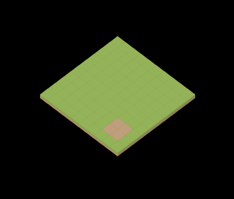
And here is the scaled grid after we rotate grid by 45 degree and the scale the grid so that the tiles overlap each other correctly.
Rotating to different view points
Armed with this knowledge, rotating the view for each different orientations of the grid is as easy as applying another rotation transform before we convert the grid into the isometric projection.
If we intend to mimic the rotation of SimCity 3000, there are only four set rotations, one for each corner of the map. This means from our initial view we will either be rotating 90 degrees clockwise, 90 degrees counter clockwise, or 180 degrees.
In matrix form, a rotation matrix would look like so:
$$ R = \begin{bmatrix} \cos(\theta) & -\sin(\theta) \\ \sin(\theta) & \cos(\theta) \\ \end{bmatrix} $$
Applied to some point (x, y):
$$ \begin{bmatrix} \cos(\theta) & -\sin(\theta) \\ \sin(\theta) & \cos(\theta) \end{bmatrix} \begin{bmatrix} x \\ y \\ \end{bmatrix} $$
And multiplied out:
$$ x' = x \cos(\theta) - y \sin(\theta) \\ y' = x \sin(\theta) + y \cos(\theta) $$
Now in code, this would look like so for some angle rot:
1 let cos_rot = Math.cos(rot);
2 let sin_rot = Math.sin(rot);
3
4 let rx = (cx * cos_rot) - (cy * sin_rot);
5 let ry = (cx * sin_rot) + (cy * cos_rot);
For each rotation event, all we need to do is update the rot angle that is
used to rotate the initial view and update the placement of each tile. As long
as we have an idea of how large our grid will be, we can apply these transformations
no matter where we're viewing the grid and have the terrain correctly rotate at the
location we're viewing.
Putting it all together
Combining the rotation with the earlier scaling and isometric projection, we get the following code:
1 // Center grid on the origin
2 let cx = x - GRID_WIDTH;
3 let cy = y - GRID_HEIGHT;
4
5 // Rotate around new origin
6 let cos_rot = Math.cos(rot);
7 let sin_rot = Math.sin(rot);
8
9 let rx = (cx * cos_rot) - (cy * sin_rot);
10 let ry = (cx * sin_rot) + (cy * cos_rot);
11
12 // Scale and rotate one last time to get into iso view.
13 // NOTE: Since a rotation of 45 degrees makes it so
14 // sin = cos = 0.707, I factor out the value since all
15 // it's doing is scaling the grid down.
16 let px = (rx - ry) * TILE_WIDTH / 2
17 let py = (rx + ry) * TILE_HEIGHT / 2;
18 let pz = -(rx + ry);
19
20 return [px, py, pz];
And there you have it! We've built an isometric view that also allows us to rotate everything however we please.